Illuminance View
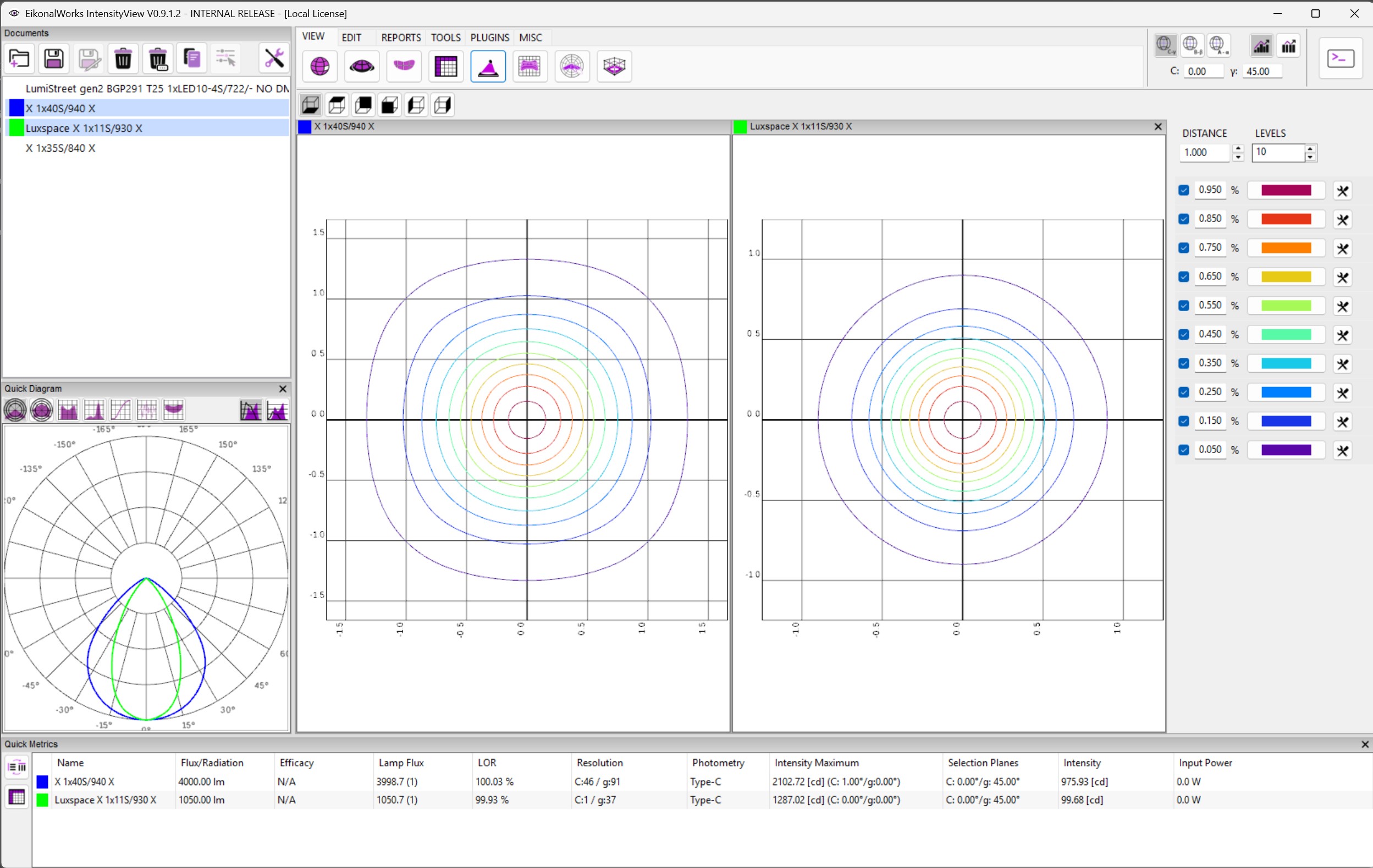
The Illuminance View calculates and plots illuminance on a selected projection plane. It is useful for comparing projected beam behavior at a specified distance.
Projection Direction
The direction buttons select the projection plane: bottom, top, back, front, left, or right. Changing the direction updates all displayed illuminance charts.
Distance
DISTANCE defines the throw distance used for the illuminance calculation. The value must be positive and is applied to all currently displayed charts.
Levels
LEVELS controls how many isolux levels are generated. The level list below the controls can then be used to inspect and adjust the resulting contour levels.
Isolux Level List
The level list displays the generated illuminance contour levels and their colors. Changes to level settings are applied to the displayed charts.
Focus Selection
Clicking a chart position updates the selected focus direction in the current photometric coordinate system. This allows the illuminance view to drive the same shared focus point used by other views.