Rendered Illuminance View
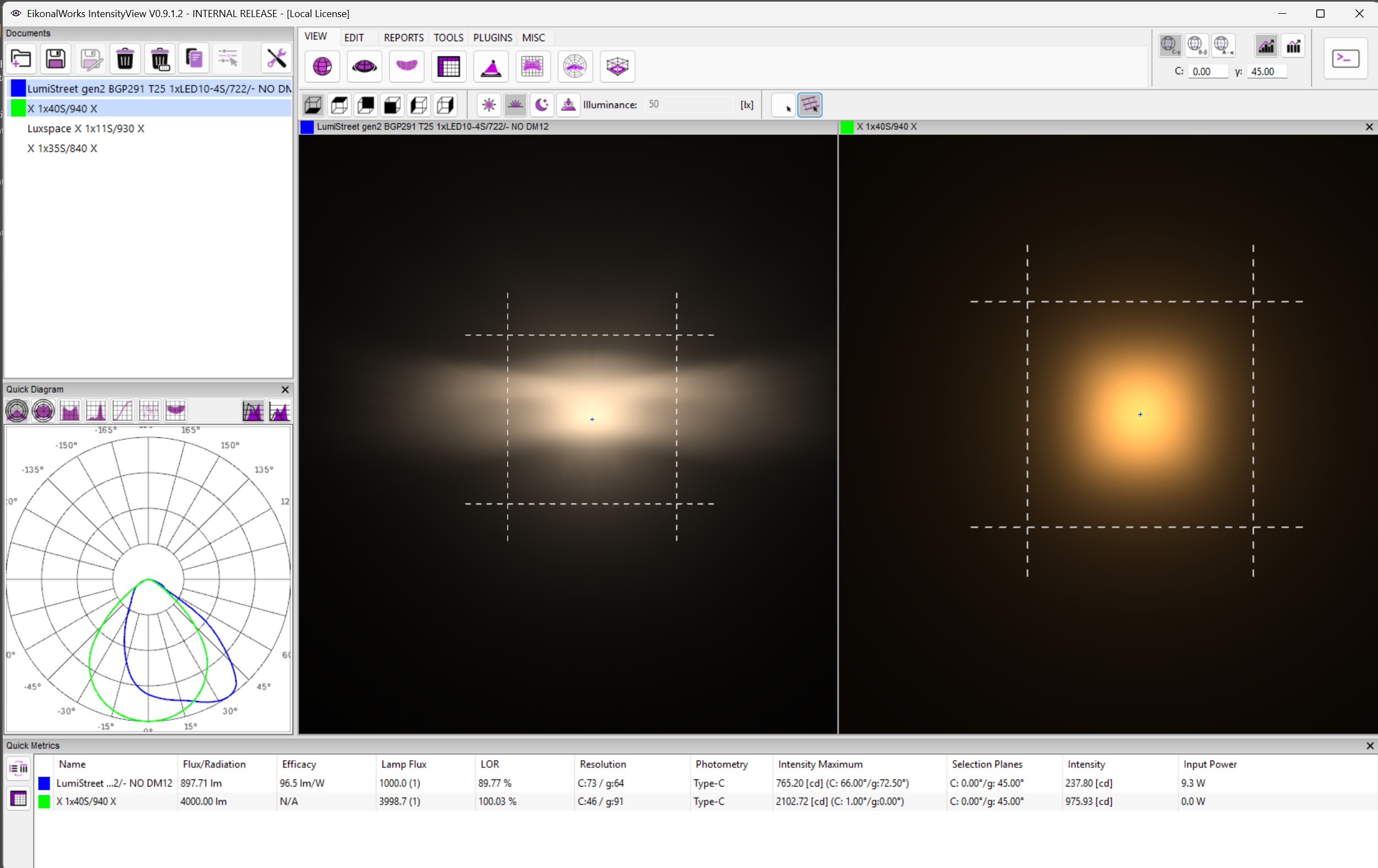
The Rendered Illuminance View renders the apparent illumination and color appearance on a selected projection plane. It is intended for visual inspection of illuminated surfaces rather than numeric isolux reporting.
Projection Direction
The direction buttons select the rendered plane: bottom, top, back, front, left, or right. The selected orientation controls how rays are projected onto the rendered surface.
Eye Adaptation State
The exposure buttons select the adaptation illuminance used by the rendering model.
- Photopic Exposure: uses a bright-light adaptation level.
- Mesopic Exposure: uses an intermediate adaptation level.
- Scotopic Exposure: uses a low-light adaptation level.
- Custom Exposure: enables the Illuminance field so a custom adaptation illuminance can be entered.
Average Adaptation Illuminance
The Illuminance field represents the average adaptation illuminance in lux. It affects the rendered color appearance because human color perception changes with eye adaptation state. At low adaptation levels, colors desaturate and shift toward scotopic or mesopic perception; at higher adaptation levels, photopic color rendering dominates.
Overlay
- No Overlay: hides the alignment overlay.
- Show Overlay: displays the projection overlay to help inspect orientation and alignment.
Focus Selection
Clicking a rendered point converts the selected pixel back into a normalized direction and updates the shared focus point. Empty pixels select the default zero direction used by the view.