EikonalWorks User's Manual
  • Workbench
  • IntensityView
Search Results for

    Show / Hide Table of Contents
    • Introduction
    • Installation and License Activation
    • User Interface
      • Keyboard Shortcuts
    • Supported File Formats
      • IES LM-63 Files
      • EULUMDAT Files
      • PHILLUM Files
      • EikonalWorks Intensity Files
      • IES TM-14 Files
      • IES TM-33 JSON Files
      • IES TM-33 XML Files
      • GLDF Files
    • View Modes
      • Sphere View
      • 3D View
      • 2D Map View
      • Table View
      • Illuminance View
      • Isocandela View
      • Polar And Cartesian Diagram View
      • Rendered Illuminance View
    • Edit Tools
      • Properties
      • Property Fields
      • Photometry Type And Resolution
      • Geometry Editor
      • Rotation
      • Symmetrize
      • Automatic Alignment
      • Smoothing And Denoising
      • Scale
      • Combine
      • Photometry Packaging Builder
    • Reports
      • UGR Table
      • UGR Chart
      • Soellner Diagram
      • Luminance Table
      • Utilization Factor Table
      • Uniformity Table
      • Zonal Lumen Table
      • Beam Spread
      • Luminaire Classification System
      • IES Roadway Report
      • Roadway Applicability
      • Color Plot
    • Tools
      • Photometry Modification Tool
      • Roadway Editor
      • Roadway Calculator
      • Roadway Generator
      • Roadway Optimizer
    • Plugins
      • LightTools Link
    • Miscellaneous
      • License Management

    Luminance Table

    Luminance Table

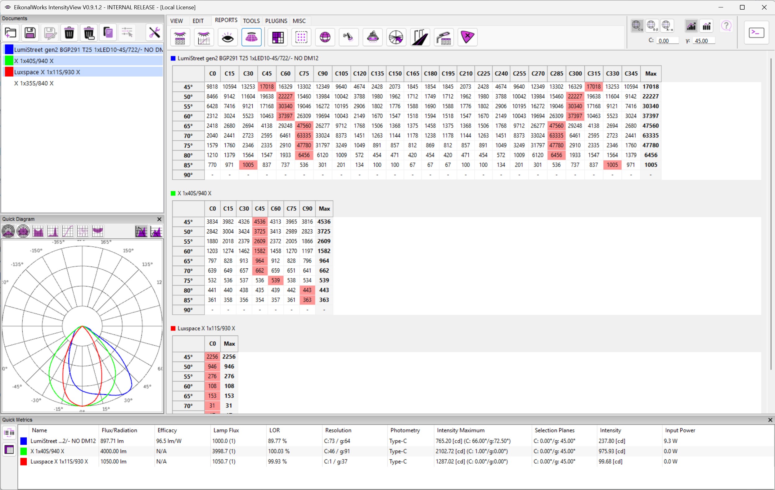
    The Luminance Table report calculates luminaire luminance for the selected photometries and presents it as tabular angular data.

    Luminance is calculated from luminous intensity divided by the apparent luminous area in the observation direction. In simplified form:

    L = I / A_projected
    

    I is luminous intensity in candela and A_projected is the apparent emitting area seen from the observation direction. The result is shown as luminance, normally in cd/m^2.

    Geometry Dependency

    The report depends on valid emitting geometry. A point source or missing emitter area cannot represent real luminance, because the projected area becomes undefined or too small. Use the Geometry Editor to define realistic emitter dimensions before using this report for glare or compliance work.

    Reading The Table

    High luminance at high observation angles is usually the most important glare risk. Compare the table values with project or standard limits for the relevant viewing angles.

    In this article
    Back to top Generated by DocFX