EikonalWorks User's Manual
  • Workbench
  • IntensityView
Search Results for

    Show / Hide Table of Contents
    • Introduction
    • Installation and License Activation
    • User Interface
      • Keyboard Shortcuts
    • Supported File Formats
      • IES LM-63 Files
      • EULUMDAT Files
      • PHILLUM Files
      • EikonalWorks Intensity Files
      • IES TM-14 Files
      • IES TM-33 JSON Files
      • IES TM-33 XML Files
      • GLDF Files
    • View Modes
      • Sphere View
      • 3D View
      • 2D Map View
      • Table View
      • Illuminance View
      • Isocandela View
      • Polar And Cartesian Diagram View
      • Rendered Illuminance View
    • Edit Tools
      • Properties
      • Property Fields
      • Photometry Type And Resolution
      • Geometry Editor
      • Rotation
      • Symmetrize
      • Automatic Alignment
      • Smoothing And Denoising
      • Scale
      • Combine
      • Photometry Packaging Builder
    • Reports
      • UGR Table
      • UGR Chart
      • Soellner Diagram
      • Luminance Table
      • Utilization Factor Table
      • Uniformity Table
      • Zonal Lumen Table
      • Beam Spread
      • Luminaire Classification System
      • IES Roadway Report
      • Roadway Applicability
      • Color Plot
    • Tools
      • Photometry Modification Tool
      • Roadway Editor
      • Roadway Calculator
      • Roadway Generator
      • Roadway Optimizer
    • Plugins
      • LightTools Link
    • Miscellaneous
      • License Management

    Uniformity Table

    Uniformity Table

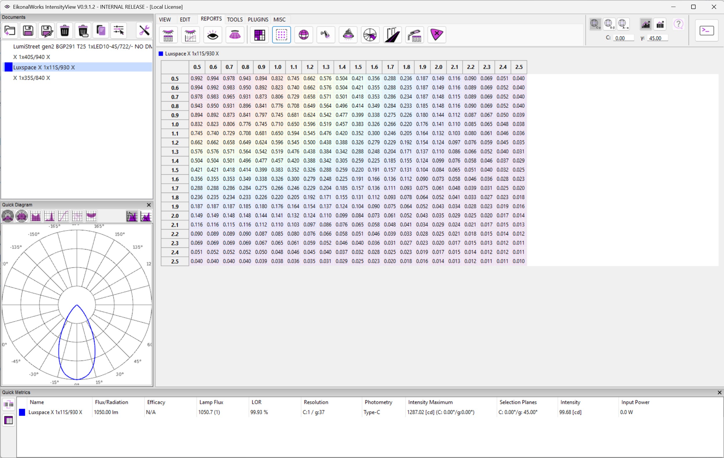
    The Uniformity Table reports illuminance uniformity for standard spacing cases. It helps estimate how evenly a luminaire can light a working plane when multiple luminaires are arranged in a regular grid.

    Uniformity is normally expressed as ratios such as minimum-to-average or minimum-to-maximum illuminance. Higher values mean a more even result.

    Spacing Interpretation

    Each spacing case represents a different distance between luminaires relative to mounting height. Dense spacing usually improves uniformity. Wider spacing may still be acceptable for broad distributions but can expose dark zones for narrow or sharply peaked photometry.

    Practical Use

    Use this report as an early comparison tool. For final design decisions, verify the selected layout with the project geometry, maintenance factor, mounting height, and required illuminance criteria.

    In this article
    Back to top Generated by DocFX